Semi-Automatic Spot Welder

Sometimes I feel the need for a spot welder for welding battery tabs. Since soldering batteries can damage their chemistry and commercial spot welders are too expensive, I decided to build my own from scrap. I don’t recommend doing this if you are not confident with electrical stuff since this project ivolves mains voltage and high currents which result in an overall power of around 1000W! You have been warned!


Microwave oven transformers (MOTs) can be obtained for free and have great potential to be used or abused in various projects. One popular use of MOTs is in DIY spot welders. One has to remove the secondary (high voltage) winding and sqeeze in 2-3 turns of heavy gauge copper wire in order to get 1.5-3V @ ca. 400A. There is an infinite amount of information on how to do this online so I won’t cover it too deeply.
I was able to squeeze 2.5 turns onto the core using ca. 8mm thick stranded copper wire. The electrode blocks are made from pure copper (12x12x50mm copper bars) to minimize resistance and sink the heat. The lugs that connect the wire to the blocks can be made from copper sheets or copper pipe. The welding electrodes are 4.5mm solid copper wire with pointed tips. I had to experiment a little with electrode distance and tip geometry. 3-10mm distance and round tip geometry are probably good starting points.
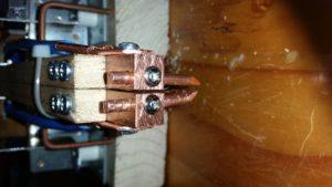


In order to get consistent welds, some parameters have to be controlled with the most important being mechanical force of the electrode to the workpiece and duration of the high current pulse. The idea behind resistance spot welding is that the spots where electrodes touch the workpiece are the areas of highest electrical resistance and therefore they heat up, melt and fuse together. My welder is built in a “series configuration” which means that both electrodes are at the top as opposed to the alternative variant where one is at the top end the other at the bottom. It is important for both welding electrodes to have near-equal mechanical force on the workpiece and therefore both are spring-loaded individually. Two microswitches in series ensure that the same force on every electrode is applied every time. Only when both microswitches are triggered, the welding pulse is applied. Afterwards the system waits for some seconds until the next weld can be performed. Note that the cable tie on the pictures only holds both arms together losely. They are still able to move away from each other for at least 10mm which is sufficient.

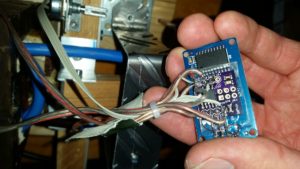


An Attiny85 breakout board takes care of pulse timing. The pulse duration can be adjusted with a 5k potentiometer. A TM1637-based 4 digit 7 segment display shows its duration in milliseconds. A solid state relay for AC voltage turns on the MOT for the set duration. The control circuit is powered by a small 5V 1A AC-DC converter of asian origin. All GPIO pins of the Tiny are finally occupied. The Attiny85 was programmed using the Arduino IDE and while the code is primitive, it does its job well:


//Spot welder controller, simple "blocking code using delays
//uses TM1637 4digit LED display board
//D2: data, D1: clock of TM1637
//D0: solid state relay to switch the MOT
//A3: potentiometer (5k to 50k)
//D4: trigger (2 microswitches in series for each welding electrode)


#include <Arduino.h>
#include <TM1637Display.h>

// Module connection pins (Digital Pins)
#define CLK 1
#define DIO 2
#define SSR 0
#define POT A3
#define TRIG 4

#define maxPulseLength 500

int weldingTimer = 400; //in ms
int pauseTimer = 4000;
int addr=0;
TM1637Display display(CLK, DIO);

void setup() {
  display.setBrightness(7);
  pinMode(TRIG, INPUT_PULLUP);
  pinMode(SSR, OUTPUT);
  digitalWrite(SSR,LOW);
  //value = EEPROM.read(addr);
}

void loop() {
  int anVal = analogRead(POT);
  weldingTimer=map(anVal,0,1024,0,maxPulseLength);
  display.showNumberDec(weldingTimer);

  if(digitalRead(TRIG)==LOW){
    digitalWrite(SSR,HIGH);
    delay(weldingTimer);
    digitalWrite(SSR,LOW);
    delay(pauseTimer);
  }
}

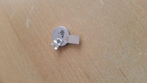
This system has plenty of power. It’s probably even over-powered for battery tab welding so make sure to start with small welding pulses of around 20ms and increase until the weld sticks well. With 70ms and an electrode distance of 3mm I managed to burn a hole through an empty coin cell in an attempt to weld a 0.1mm nickel strip to it. Experiment on scrap metal before you proceed to serious business such as 18650 cells.

OpenBCI with Plessey EPIC Electrodes

Conventional electrodes on EMG/EEG/ECG systems require low contact impedance and therefore often skin preparation is needed. Disposable electrodes can become expensive over time and to improve conductivity, with many electrodes gel has to be used, which is annoying. Capacitive electrodes have the advantage of being reusable and due to their etremely low contact impedance they can make biopotential measurements unobtrusive by incorporating them into seats or measuring through clothing.


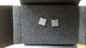
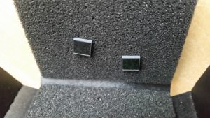
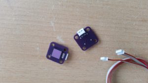
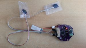
After coming across commercial capacitive electrodes I was curious how they perform and made a carrier board for the QFN electrodes. The devices require bipolar power supplies from +- 2.4 to 5V so they are compatible with the OpenBCI V3 boards which have +-2.5V. The PS25255 is the type I finally purchased because it is low power and low gain.


The things look very interesting. The actual contact surface has a mirror finish and looks like silicon. Strangely there is a gap between the electrode contact area and the rest of the package. I think this might cause problems because the electrode is designed to be in direct contact with skin and dirt might accumulate inside this gap.
The 4 contacts (VCC, VSS, GND and SIGNAL) are on the bottom side of the QFN package and therefore my approach of mounting them to the PCB is by having plated holes in the pads and soldering from the bottom side. Use sufficient amounts of flux and the solder reflows down to the contacts and you have a perfect connection.


As a connector a 4-pin JST-style connector with 1.25mm pin pitch was used. I mounted it in a right angle to make the sensor flat. Crimping the female connectors using a PA-09 crimping tool was a challenge because they are so tiny.
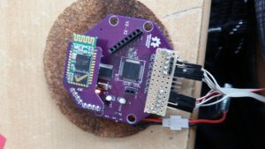
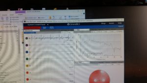
Finally, I assembled an adapter board to break out the + and – 2.5V of the OpenBCI ‘Cyton’ board (AGND is already broken out on the right angle header) and tried to acquire some ECG. The signal outputs of both electrodes were connected to channel 1 an its gain was lowered to 2x (the PS25255 electrode itself already has a gain of 10). Also the channel has to be disconnected from SRB1 in the channel settings to make it ‘bipolar’.


If placing the electrodes directly on the skin you get quite good results without any skin preparation. I was also easily able to acquire EEG by placing one eclectrode on the forehead and the other one on the neck. Hair distorts the signal too much.


After putting both electrodes into plastic bags I was still able to acquire an ECG signal, but the signal was very sensitive to movement. Attempts to measure through a t-shirt were only successful if strong pressure was applied.
In all my experiments I did not use a drien right leg circuit or the bias output of the OpenBCI. Instead, only the software notch filter was enabled.


As a conclusion, I’d say that this was an interesting experiment, but 20$ per electrode seems a bit much for my hobby grade experiments. The Plessey EPIC electrodes seem to be usable for ECG, but their inability to penetrate hair for multichannel EEG is a little disappointing. It’s hard to tell how long the will last due to their peculiar packeage design. I will try some active electrode designs from the OpenEEG project with the OpenBCI soon, since they are easy to make, cheap and you can attach a comb electrode to it to be able to acquire EEG through hair hopefully more reliably than with passive electrodes.

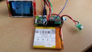
Raspberry Pi Zero Lipo Fuel Gauge With Safe Shutdown

The Pi Zero (and Zero W) are quite tolerant in respect to their power requirements. They can even be run from a LiFePO4 battery that has a voltage range of 3.6 to 2.5V. LiPo batteries are better-suited as their voltage ranges from 4.2 down to about 3V. When running the boards from the blank cell (it should have protection circuitry!), they last even longer because fewer losses occur since there is no boost converter in the system. In fact, the 5V is only needed for the USB host, although many devices are supposed to work from voltages down to 3V.


Unfortunately, these single board computers lack power management and don’t have shutdown buttons and there are not that many simple and cost-effective solutions for these problems. https://www.tindie.com/products/xorbit/lifepo4weredpi/ is one nice example, but unfortunately not fully open source.
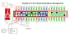
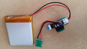
My idea was to combine a MAX17043 LiPo fuel gauge with a pushbutton and a LiPo charging circuit to create a battery and safe shutdown management add-on for the Pi Zero.


The little board occupies only the first 10 pins and uses only GPIO4 and SDA + SCL. Design files for the tiny custom TP4056 charger board can be downloaded as a .zip archive:


TP4056mCH

The Python script the make the thing work is attached below. Add it to rc.local to execute on startup.


#!/usr/bin/python

#Python Script for MAX17043 fuel gauge and safe shutdown button
#in order to execute on startup add the following line to /etc/rc.local
#(sleep 10;python /home/pi/fuelgauge.py) &
#assuming that fuelgauge.py is in /home/pi 
#sleep 10 is probably not necessary

import RPi.GPIO as GPIO
import smbus
import time
import os


#threshold in % below which the pi gets shut down
threshold=15.0
buttonPin=4
# I2C-Adddress of MAX17043
address = 0x36

#registers
VCELL_REGISTER=0x02
SOC_REGISTER=0x04
MODE_REGISTER=0x06
VERSION_REGISTER=0x08
CONFIG_REGISTER=0x0C
COMMAND_REGISTER=0xFE

#  open the bus by creating an instance
MAX17043 = smbus.SMBus(1)

#set up GPIO for shutdown button
GPIO.setmode(GPIO.BCM)
#Using GPIO nr 4
GPIO.setup(buttonPin,GPIO.IN,pull_up_down=GPIO.PUD_UP)

def reset():
    MAX17043.write_byte_data(address, COMMAND_REGISTER, 0x00)
    MAX17043.write_byte_data(address, COMMAND_REGISTER, 0x04)

def quickStart():
    MAX17043.write_byte_data(address, MODE_REGISTER, 0x40)
    MAX17043.write_byte_data(address, MODE_REGISTER, 0x00)

#get state of charge
def getSOC():
    # Konfiguration des MAX17043
    MSB= MAX17043.read_byte_data(address, SOC_REGISTER)
    LSB = MAX17043.read_byte_data(address, SOC_REGISTER)
    percentage= MSB+ LSB/256.0
    #print percentage
    if percentage < threshold:
        os.system("sudo shutdown -h now")


#Arduino map function for convenience
def arduino_map(x, in_min, in_max, out_min, out_max):
    return (x - in_min) * (out_max - out_min) // (in_max - in_min) + out_min

#setup
reset()
quickStart()

# Loop
while True:
    getSOC()
    time.sleep(1.5)
    #shutdown if button is pressed and held
    if (GPIO.input(buttonPin)==0):
        os.system("sudo shutdown -h now")


if __name__ == "__main__":
   main()