I’ve recently found a single-use medical grade pressure sensor, as used in invasive catheter blood pressure measurements in critical care medicine.
It has got 4 output terminals as you can see in the picture below where one can simply insert small 1mm nails…
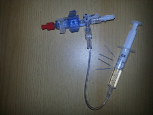
The internal configuration seems to be a Wheatstone Bridge and therefore it has to deliver an analog output. So some measurements of the resistances between the terminals were made which quickly led to the following test setup:

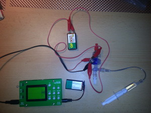
With 7.2V connected to the sensor the amplitude of the output voltage is at about 0.1V
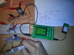
A simple opamp-based differential amplifier was used to amplify the output.
Monthly Archives: June 2014
Multistage Coilgun Rifle
Building something powerful and dangerous probably lies in the nature of a man. Even (or especially) some MIT professors are passionate about powerful technical devices such as chain saws 🙂 And there’s also some competition on the internet in the world’s coilgun arsenal, where devices from all over the world are sorted and several parameters can be compared with others. One major aim is to gain good efficiency, which would be around 4%, while still keeping it portable. Some years ago I wanted to enter the heavy rifle class in this league and so this project was born. Just like its little brother, this coilgun was also accepted in world’s coilgun arsenal.
This device has been in the benchtop testing for a while and I’ve been working slowly but very persistently on it. You really need a lot of patience if you want to construct something like this. All coils and transformers are hand-wound and the capacitor banks consist of 106 small caps in total. You also have to be prepared to encounter difficulties along the way and probably even burnt parts and injuries if you aren’t careful. I would not recommend you to buid a multistage coilgun if you don’t have experience in electronis! Also, dangerous voltages and dangerous flying metal parts are involved, so bear this warning in mind!
This blogpost is a documentation of the construction process:
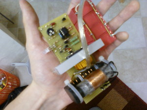
This is the capacitor charger the device is based on. The Idea and schematic for it came from uzzors2k. It is based on the Mazzilli Flyback Driver and has a lot of power and efficiency running off 12V. The secondary of the flyback transformer was re-worked with 4layers x 240 turns with 0.3mm enamelled copper wire. An adjustable coparator circuit turns the charger off when the threshold is reached.
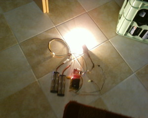
I liked this circuit so much that I’ve built 2 versions of it trying to make it more compact. Here is the socond one showing off its power: a 100W lightbulb enlightened gets pretty bright from the 14,4V NiMH batteries.
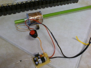
What we’ve got here is the first coil, its capacitor bank, the protection diodes and the triggering circuitry using 3 2N6509 SCRs in parallel with a 7805 for a 5V supply. The big red button is the trigger smiley
Coil data: I don’t quite remember the exact amount of turns, but it has to be something around 350 in 7 layers for the first stage, which makes the coil about 5 cm long when using 1mm wire and a cylindrical geometry. In the picture it has some more layers, which I removed in order to reduce resistance and increase efficiency when working with the chosen capacitor bank. The next coils get shorter and shorter with less and less turns for faster discharge, since all cap banks are the same size. The steel washers at each end of the coil are slotted to limit Eddy Currents.
Capacitor bank: I’ve found really cheap 68µF 400V electrolytic caps which come in packs of 10, so I’ve made banks with a total of 1088µF. They are capable of storing 87J of energy when charged to 400V.
Switching: 3x 2N6509 in parallel. Each SCR is capable of handling a surge current of 250A.
Barrell: almost transparent PVC tube with thin walls and 10mm inner diameter, originally for aquarium purposes. The light beam gets through the material without holes.
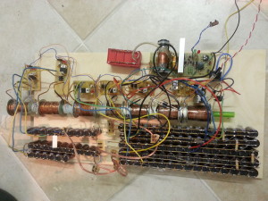
This is the Coilgun in its current stage of construction.
All 4 coils are wound, the optical detection circuits (which are the same as in my pistol) are working, all 4 stages are cooperating quite well!
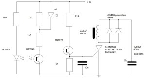
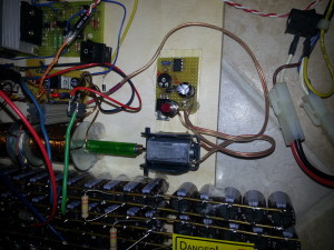
As you can see each stage has got its on bridge rectifier (consisting of 4x UF4007) and 330K resistor for slow discharge in case it doesn’t get activated. 2 cap banks have got neon bulbs installed to reliably detect that they are charged even if the power supply is disconnected. The other banks will be equipped with neon bulbs as well, as soon as I get a couple of them.
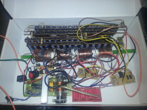
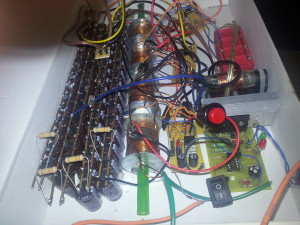
I know, I should not keep that thing that messy, because the danger of short circuits is high, but I’ll clean it up as soon as I’ve got the time.
The gun is ready to be installed into a rifle-shaped casing, but actually I’m playing with the thought of installing an additional fifth stage and add 340µF to each cap bank. This will result in 500J (!!) in total distributed on five stages. A worthy aim smiley.
Update:
The device has been fixed on 8mm plywood for safe benchtop testing. Also, a couple of videos have been recorded.
Every stage was upgraded with 340µF for a total of 400J! The improvement was not as good as I thought, but as soon as the chronograph is ready, some precise measurements have to be performed. Charge time is less than 10 seconds.
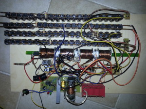
Now some more results:
Exit hole:
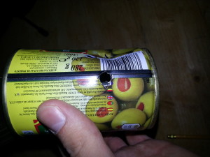
Update:
Ok, since I had many spare capacitors and stuff for the photodetector circuits, I decided to add (yeah, right!) 3 more stages!! Upscaling is not a big deal if you keep following an approved concept.
The 5th – 7th stage were supposed to have coils with greater wire gauge (1.8mm) for further decreasing Ohm’s resistance and allowing for greater currents. Besides that a slightly different coil concept was followed in the “second half” of the coilgun: I decided to have fewer and fewer layers but increasing coil lengths to have the acceleration path increase and the pulse duration decrease to account for the fast accelerating projectile.
After the fifth stage I ran out of 2N6509 SCRs and used BT145 – 800Rs in stacks of three. They are rated for 300A surge current each, which is almost one kA per stage.
The fifth and seventh stage got me into some turbulences while testing the whole setup. The fifth coil shorted on two points on the steel washer, because the insulation layer got damaged there. This bug could be corrected easily though, removing the washer and using more epoxy.
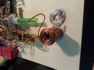
The seventh stage burnt the protected diodes (and some SCRs :() since i ran out of good ol’ UF5408 and had to use different ones. When the parts are replaced, the otherwise completed seventh stage will also work. Edit: since the protection diodes kept burning, I decided to use a smaller 50J bank with only 10 68µF caps and copletely leave the diodes. With a properly sized power dissipation resistor the smaller bank reaches its 400V when its bigger bros are done.
I think this device will not have more stages, because it is dedicated for portable use some day and therefore any more increase in in size is kind of making it inpractical.
An idea that came to my mind is simply usind a DC motor with a small neodymium magnet for projectile rotation which is supposed to stabilize its trajectory. I’ve added PWM speed control to it so that it doesn’t spin too fast to stick to the projectile. Whether or not the trajectory of the bullet is affected by this concept remains to be tested over longer firing distances of, say, 10m.
A video of 6 stages in action (projectile = 8 nails!):
Update:
The guts have been built int an enclosure, finally. It consists of PVC for the most part and is held together using Tangit, which is an adhesive that welds this kind of plastic together. Only the casing of the charging circuitry is made of ABS, which sticks to PVC using the same glue though. Well, and the enclosure of the acceleration unit is a PP pipe which had to be screwed to the remainder as it is not affected by the solvent of the glue at all.
These are the final banks that will be used:
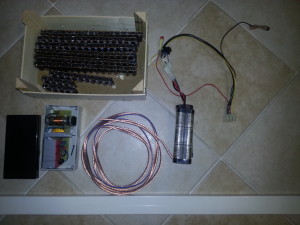
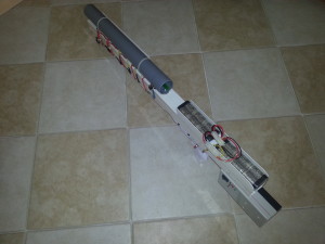
Below you can see the standard polypropylene pipe that will house the coils and light traps. The coils have been wrapped with sheet iron. Some authors claim improvement of performance. The diode bridge rectifiers and switching circuits will be built into a 40mm wide PVC cable enclosure at the bottom of the device.
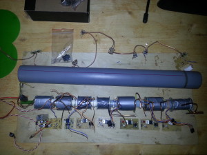
The cap banks for the first 6 stages are hidden in the double compartment shaft, the triggers and rectifiers are mounted below. The grip is a Nintendo Wii gun shaft for the Wii remote. It seems to be derived from the Walther P99 and is just incredibly ergonomic. It was just slightly trimmed, equipped with a reset switch from a computer and screwed to 2 massive PVC brackets that have been glue-welded to the PVC main shaft and we’re done.
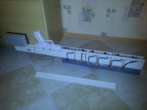
The cap bank, trigger circuit, rectifier and power dissipation resistor have been built into another piece of PVC cable enclosur and mounted to the side, since I didn’t want the finished device to exceed 1 meter in length.
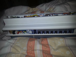
The battery housing was formed from the remainder of PVC profile that I had. The battery packs are held in place with Velcro strips.
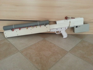
And of course, some words on safety precautions are appropriate, especially if one owns a DIY laser-engraving CNC machine 😉
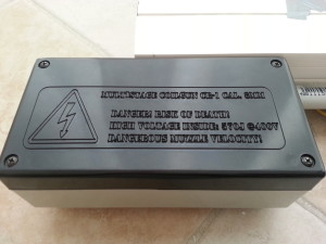
Final specs:
the first 6 stages have capacitor banks with 16 caps à 68µF which store 87 Joule each when charged to 400V. The seventh stage’s capacitance is only 680µF which makes 50J @ 400V. Some power is dissipated through a 6k 5W resistor to make sure that after the same amount of time all stages have the same voltage. The overall stored electrical energy for all 7 stages is 572J. Charge time at 14.4V is below 10s.
A big screwdriver bit weighs almost exactly 10g. With a calibrated ballistic chrono a velocity of 50m/s was determined which results in a muzzle energy of 12.5J.
So overall efficiency is 2.1%
Tesla Coil

I’ve built this mall ZVS-Driven Spark Gap Tesla Coil some years ago. It has got a simple dual spark gap, a MMC (multi mini cap) with a total capacitance of 2,27nF. The secondary coil has got 1065 turns of 0,2mm enamelled copper wire and a diameter of 21mm.
The primary coil is adjustible with a crocodile clamp.
The flyback transformer is powered using the ZVS (zero voltage switching) technique. This driver is also known as the Mazzilli Driver….just google it and you’ll find out, in case you don’t know what this is about ;). It can push a flyback to its limits…I’ve never powered this lil’ thing above 50W though, I don’t know, maybe soon 😉
You get nice 10cm long streamers from this device when powered off a 3S LiPo battery.
Here’s the device at 22V (6S LiPo Battery):
Coilgun Pistol
50J Multistage Coilgun Pistol cal. 6mm – a project I made real 5 years ago. The construction process of this pistol is quite well-documented on photos. Enjoy….


Readily wound coils: the first one uses 0,8mm enamelled copper wire (forgotten how many turns it had, probably around 200) and has the biggest capacitor bank. The other 2 coils have thinner wire, but also more turns for a stronger magnetic field. For faster discharge and smaller dimensions their capacitor banks are smaller.
The TO220 Parts are SCRs (2N6509) for 250A surge current. The phototransistors with their IR-LEDs are also waiting to be built in. The circuit board contains single-transistor circuits for the optical projectile detection. A 7805 is also on board.
The gun has got 2 power supplies: a 9V battery for the control circuit and laser sight and AA batteries for charging the capacitors…

Here we have the completed accelerator stage with optical projectile detection, coils and Thyristors.

This photo contains pretty much all parts as well as the schematic diagram. You can see where most of the capacitors are going to live. The 4 caps in parallel are all for the first stage. Right above them you see the tiny charging circuits. I’ve extracted them from three disposable cameras and re-soldered the most important parts (only the tiny transformer, one resistor and the transistor as well as the diode) on a piece of perfboard. Each stage has got its own charging circuit. Stage 1 and 2 are Kodak-derived and stage 3 is Fujifilm-derived. It takes about 40s to charge the caps to about 330V, depending on the AA batteries you use.
The handpiece is from an old airsoft gun by the way. The trigger switch is also built in already (taken from an old computer).

A close-up to the charging circuitry with some more wiring accomplished. The LEDs and the neon bulb at the end of the wires are for charge detection. Kodak uses LEDs, Fujifilm those neon bulbs.

Tight, but it fits!

Some insulation was done, a red laser mounted and the bottom of the accelerator stage covered with aluminum sheets, which have been cut out of a spray can :).
A typical shot with a “stabilized” pointed projectile. You can see that it penetrates from larger distances.
Simply a big iron slug cal. 6mm.
An exact measurement of the muzzle velocity has to be done some day to determine efficiency, but it seems not bad at all. The thing even punches holes into tin.

Mendocino Motor
A Mendocino Motor is an optically commutated, magnetically levitating, solar powered Rotor.
This one consists of 3,6mm plywood and was completely machined with my CNC mill. The Design has been accomlished in Google Sketchup, the G-Code was generated with the Phlatscript plugin.


The dimensions can be estimated from the screenshots. After milling the parts are taken out of the plywood sheets (cut the tabs that hold them in place) and just pressed together, no glue necessary!
The 2 coils have ~100 turns each with 0,3mm enamelled copper wire. The solar cells are capable of delivering 200mA at 0,5V.
At the end of the rotor that has contact to the mirror a tip of a pencil has been inserted (see pic above) to minimize friction, due to the lubricating properties of graphite.
Sketchup files (1 for the base and 1 for the rotor):
SketchUp files
Compact Arduino ECG Monitor
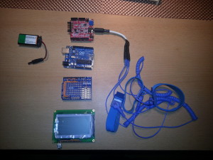
As a medical professional I’ve always been interested in experimenting with biosignals. I’ve made a couple of attempts to build the analog part of a simple ECG amplifier, but encountered some obstacles. Some day I’ve found this well-designed ECG/EMG shield by Olimex which uses an instrumentation amplifier and fits on an Arduino board. It comes with some sample code as well. I was suprised that it uses old C commands such as cbi, sbi, outp() and inp() but I learned a lot while going through the code and understanding it. It was originally written to interface with the ElectricGuru EEG-software via the serial port and processes the input signal of up to 6 of those shields, since they can be stacked together easily.
First of all I wanted to play with the ECG signal and since I had just figured out how to use a KS0108 GLCD, I just combined both to make this neat biofeedback device. One obstacle I came across when trying to connect the LCD to a microcontroller is figuring out which model it is! So take a look at the data sheet or whatever, because there are 3 types of those 20pin displays! The glcd library documentation on contains a table that visualizes the pinouts. Because there are many wires you have to mess around with, I simply soldered a female header on a Proto Shield and hard wired everything.
Another function I wanted to implement is QRS-detection. QRS complexes are those pointed, high spikes in an ECG which represent the electrical activity in the main muscular mass of the heart (myocardium). Their detection is quite easy by measuring the biggest slopes and and can give a more or less reliable representation of one cycle of cardial action. My code calculates the time between 2 detected “heartbeats” (RR interval) and displays that as the heart rate. This has the advantage over averaging a couple of heartbeats that you can directly observe how your heartbeats vary.
Many interestings things can be done with this kind of setup. The next step will be logging the ECG by either writing it to a SD card or sending the data to a PC via bluetooth and logging there (patient insulation from mains powered devices and less disturbing influence from the mains line). This is a very powerful tool for diagnostic purposes. For example arrythmias that occur under certain circumstances can be diagnosed or heart rate variability can be measured, which can give you information on the influence of the autonomic nervous system on cardial action…
Interrupt-based code, modified for use with the glcd:
/**********************************************************/
/* Demo program for:                                      */
/*    Board: SHIELD-EKG/EMG + Olimexino328                */
/*  Manufacture: OLIMEX                                   */
/*  COPYRIGHT (C) 2012                                    */
/*  Designed by:  Penko Todorov Bozhkov                   */
/*   Module Name:   Sketch                                */
/*   File   Name:   ShieldEkgEmgDemo.pde                  */
/*   Revision:  initial                                   */
/*   Date: 01.02.2012                                     */
/*   Built with Arduino C/C++ Compiler, version: 1.0      */

/*EXTENDED BY insanity wolf */

/*This version is for monitoring the signal directly on a KS0108 graphical LCD display*/

/**********************************************************/
/**********************************************************
Purpose of this programme is to give you an easy way to
connect Olimexino328 to ElectricGuru(TM), see:
http://www.realization.org/page/topics/electric_guru.htm
where you'll be able to observe yours own EKG or EMG signal.
It is based on:
***********************************************************
* ModularEEG firmware for one-way transmission, v0.5.4-p2
* Copyright (c) 2002-2003, Joerg Hansmann, Jim Peters, Andreas Robinson
* License: GNU General Public License (GPL) v2
***********************************************************
For proper communication packet format given below have to be supported:
///////////////////////////////////////////////
////////// Packet Format Version 2 ////////////
///////////////////////////////////////////////
// 17-byte packets are transmitted from Olimexino328 at 256Hz,
// using 1 start bit, 8 data bits, 1 stop bit, no parity, 57600 bits per second.

// Minimial transmission speed is 256Hz * sizeof(Olimexino328_packet) * 10 = 43520 bps.

struct Olimexino328_packet
{
  uint8_t    sync0;        // = 0xa5
  uint8_t    sync1;        // = 0x5a
  uint8_t    version;    // = 2 (packet version)
  uint8_t    count;        // packet counter. Increases by 1 each packet.
  uint16_t    data[6];    // 10-bit sample (= 0 - 1023) in big endian (Motorola) format.
  uint8_t    switches;    // State of PD5 to PD2, in bits 3 to 0.
};
*/
/**********************************************************/
#include <glcd.h>
//http://www.arduino.cc/playground/Code/GLCDks0108

#include "fonts/allFonts.h"         // system and arial14 fonts are used
#include "bitmaps/allBitmaps.h"       // all images in the bitmap dir
gText textArea;              // a text area to be defined later in the sketch


#include <compat/deprecated.h>
#include <FlexiTimer2.h>
//http://www.arduino.cc/playground/Main/FlexiTimer2
#include <TimerOne.h>
//http://arduino.cc/playground/Code/Timer1

/*
Erklärung von cbi, sbi, outp und inp
Bei solchen Makros sollte man etwas mehr Klammern spendieren:

#define sbi(ADDRESS,BIT) ((ADDRESS) |= (1<<(BIT)))
#define cbi(ADDRESS,BIT) ((ADDRESS) &= ~(1<<(BIT)))
#define outp(VAL,ADRESS) ((ADRESS) = (VAL))
#define inp(VAL) (VAL)
The outb( ) function provides a C language interface to the machine instruction that writes a byte to an 8 bit I/O port using the I/O address space instead of the memory address space.
*/

// All definitions
#define NUMCHANNELS 6
#define HEADERLEN 4
#define PACKETLEN (NUMCHANNELS * 2 + HEADERLEN + 1)    //6*2+4+1
#define SAMPFREQ 256                   // ADC sampling rate 256
#define TIMER2VAL (1024/(SAMPFREQ))    // Set 256Hz sampling frequency
#define PWM_OUT 9                      // Number of pin used for generating CAL_SIG
#define PWMFREQ 10        //10Hz for Calibration signal
#define LED1  13

// Global constants and variables
char const channel_order[]= { 0, 1, 2, 3, 4, 5 };
volatile unsigned char TXBuf[PACKETLEN];  //The transmission packet
volatile unsigned char TXIndex;           //Next byte to write in the transmission packet.
volatile unsigned char CurrentCh;         //Current channel being sampled.

//~~~~~~~~~~
// Functions
//~~~~~~~~~~

/****************************************************/
/*  Function name: Toggle_LED1                      */
/*  Parameters                                      */
/*    Input   :  No                                */
/*    Output  :  No                                 */
/*    Action: Switches-over LED1.                   */
/****************************************************/
void Toggle_LED1(void){

 if((digitalRead(LED1))==HIGH){
   digitalWrite(LED1,LOW);
  }
  else{
   digitalWrite(LED1,HIGH);
  }
}

/****************************************************/
/*  Function name: setup                            */
/*  Parameters                                      */
/*    Input   :  No                                */
/*    Output  :  No                                 */
/*    Action: Initializes all peripherals           */
/****************************************************/
void setup() {

 noInterrupts();  // Disable all interrupts before initialization

 // LED1
 pinMode(LED1, OUTPUT);  //Setup LED1 direction
 digitalWrite(LED1,LOW); //Setup LED1 state

 //Write packet header and footer
 TXBuf[0] = 0xa5;  //Sync 0
 TXBuf[1] = 0x5a;  //Sync 1
 TXBuf[2] = 2;     //Protocol version
 TXBuf[3] = 0;     //Packet counter

 // ADC
 // Timings for sampling of one 10-bit AD-value:
 // XTAL = 16000000MHz
 // prescaler > ((XTAL / 200kHz) = 80 =>
 // prescaler = 128 (ADPS2 = 1, ADPS1 = 1, ADPS0 = 1)
 // ADCYCLE = XTAL / prescaler = 125000Hz or 8 us/cycle
 // 14 (single conversion) cycles = 112 us
 // 26 (1st conversion) cycles = 208 us
 outb(ADMUX, 0);         //Select channel 0
 outb(ADCSRA, ((1<<ADPS2) | (1<<ADPS1)| (1<<ADPS0))); //Prescaler = 128, free running mode = off, interrupts off.
 sbi(ADCSRA, ADIF);  //Reset any pending ADC interrupts
 sbi(ADCSRA, ADEN);  //Enable the ADC

 // Serial Port
 outb(UBRR0, 16);              //Set speed to 57600 bps
 outb(UCSR0B, (1<<TXEN0));     //Enable USART Transmitter.

 // Timer1
 // It's used for calibration signal generation: CAL_SIG via PWM.
 // CAL_SIG is used like reference signal when setting-up SHIELD-EKG/EMG's channel gain
 // During normal operation this signal is not required so it can be disabled with uncommenting te row below!
 /*
 pinMode(PWM_OUT, OUTPUT);    //Set PWM_OUT direction
 digitalWrite(PWM_OUT,LOW);   //Set PWM_OUT state
 Timer1.initialize((1000000/(PWMFREQ))); // initialize timer1, and set a 1/10 second period = 10Hz ->freq. of cal signal should be 10-14Hz (schematic)
 Timer1.pwm(PWM_OUT, 512);             // setup pwm on pin 9, 50% duty cycle
 //Timer1.disablePwm(PWM_OUT); // Uncomment if CAL_SIG is not requiered
 */

 // Timer2
 // Timer2 is used for setting ADC sampling frequency.

/*****************************************************************
Methods of the FlexiTimer2 library:

FlexiTimer2::set(unsigned long units, double resolution, void (*f)())
    this function sets a time on units time the resolution for the overflow. Each overflow, "f" will be called. "f" has to be declared void with no parameters.
    E.g. units=1, resolution = 1.0/3000 will call f 3000 times per second, whereas it would be called only 1500 times per second when units=2.
FlexiTimer2::set(unsigned long ms, void (*f)())
    this function sets a time on ms (1/1000th of a second) for the overflow. Each overflow, "f" will be called. "f" has to be declared void with no parameters.
    Shorthand for calling the function above with resolution = 0.001.
FlexiTimer2::start()
    enables the interrupt.
FlexiTimer2::stop()
    disables the interrupt.
*******************************************************************/
 FlexiTimer2::set(TIMER2VAL, Timer2_Overflow_ISR); //TIMER2VAL was (1024/(SAMPFREQ)) in ms =4, SAMPLEFREQ was 256
 FlexiTimer2::start();  //enable the Interrupt....

 // MCU sleep mode = idle.
 outb(MCUCR,(inp(MCUCR) | (1<<SE)) & (~(1<<SM0) | ~(1<<SM1) | ~(1<<SM2)));

 interrupts();  // Enable all interrupts after initialization has been completed

 GLCD.Init();
 GLCD.SelectFont(System5x7, BLACK); // font for the default text area
}

/****************************************************/
/*  Function name: Timer2_Overflow_ISR              */
/*  Parameters                                      */
/*    Input   :  No                                */
/*    Output  :  No                                 */
/*    Action: Determines ADC sampling frequency.    */
/****************************************************/
void Timer2_Overflow_ISR()    //alle 4ms wird das ausgeführt
{
  // Toggle LED1 with ADC sampling frequency /2
  Toggle_LED1();

  CurrentCh = 0;
  // Write header and footer:
  // Increase packet counter (fourth byte in header)
   //Write packet header and footer
 /**********zur Erinnerung: der Header**********
 TXBuf[0] = 0xa5;  //Sync 0
 TXBuf[1] = 0x5a;  //Sync 1
 TXBuf[2] = 2;     //Protocol version
 TXBuf[3] = 0;     //Packet counter
 ***********************************/
 TXBuf[3]++;
  //the whole packet is /6*2+4+1=17byte
  //Get state of switches on PD2..5, if any (last byte in packet).
  TXBuf[2 * NUMCHANNELS + HEADERLEN] = (inp(PIND) >> 2) &0x0F;  //2* NUMCHANNELS, weil jeder CHannel 2 byte hat damit 1024 reinpasst

  cbi(UCSR0B, UDRIE0); //Ensure Data Register Empty Interrupt is disabled.
  sbi(ADCSRA, ADIF);   //Reset any pending ADC interrupts
  sbi(ADCSRA, ADIE);   //Enable ADC interrupts.
  sbi(ADCSRA, ADSC) ;  // Start conversion!!!
  //Next interrupt will be ISR(ADC_vect)
}

/****************************************************/
/*  Function name: ISR(ADC_vect)                    */
/*  Parameters                                      */
/*    Input   :  No                                */
/*    Output  :  No                                 */
/*    Action: Reads ADC's current selected channel  */
/*            and stores its value into TXBuf. When */
/*            TXBuf is full, it starts sending.     */
/****************************************************/
ISR(ADC_vect)
{
 volatile unsigned char i;    //volatile??

 i = 2 * CurrentCh + HEADERLEN;  //also wird i auf 4 gesetzt wenn CurrentCh==0 und unten das 5. byte beschrieben,danach TxBuf[4] ([3] ist das letzte vom Header)
 TXBuf[i+1] = inp(ADCL);      //ADC data register LOW byte
 TXBuf[i] = inp(ADCH);        //ADC data register HIGH byte
 CurrentCh++;
 if (CurrentCh < NUMCHANNELS)
 {
  outb(ADMUX, (channel_order[CurrentCh])); //Select the next channel.
  sbi(ADCSRA, ADSC) ;                   //Start conversion!!! (set ADSC-bit in ADCSRA-Register)
 }
 else
 {
   //this gets executed first....prior to the stuff above
  outb(ADMUX, channel_order[0]);      //Prepare next conversion, on channel 0.
  cbi(ADCSRA, ADIE);    //Disable ADC interrupts to prevent further calls to ISR(ADC_vect). oben hiess es sbi!!!!!!
  outb(UDR0, TXBuf[0]); //Send first Packet's byte: Sync 0
  sbi(UCSR0B, UDRIE0);  //USART Data Register Empty Interrupt Enable
  TXIndex = 1;          //Next interrupt will be ISR(USART_UDRE_vect)
 }
}

/****************************************************/
/*  Function name: ISR(USART_UDRE_vect)             */
/*  Parameters                                      */
/*    Input   :  No                                */
/*    Output  :  No                                 */
/*    Action: Sends remaining part of the Packet.   */
/****************************************************/
ISR(USART_UDRE_vect){

 outb(UDR0, TXBuf[TXIndex]);  //Send next byte
 TXIndex++;
 /******hier also***
 ch0hb = TxBuf[4];
 ch0lb = TxBuf[5];
 *******************/


 if (TXIndex == PACKETLEN)    //See if we're done with this packet
 {
   cbi(UCSR0B, UDRIE0);    //USART Data Register Empty Interrupt Disable
                              //Next interrupt will be Timer2_Overflow_ISR()
 }
}


//function for fusion of the ADCL and ADCH byte

unsigned int weiterverarbeitung(volatile unsigned char high_byte, volatile unsigned char low_byte)
{
 unsigned int value = ((high_byte&0x0f)*256)+(low_byte);
 return(value);
}

/****************************************************/
/*  Function name: loop                             */
/*  Parameters                                      */
/*    Input   :  last 2 channel bytes of the packet */
/*    Output  :  to display                         */
/*    Action: Draws ECG, detects QRS, calculates HR */
/****************************************************/
unsigned long Start, Finished = 0;
float heart_rate = 0.0;
float RR_interval = 0.0;
unsigned int Delay = 9;
int thisdot = 0;
int prevdot = 0;


void loop() {


  for(int i=0; i<GLCD.Width; i++)
  {

    Finished = 0;
    unsigned int val = weiterverarbeitung(TXBuf[14],TXBuf[15]);  //using A5 and extracting the last 2 channel bytes out of the packet
    unsigned int y = map (val, 0, 1023, 64, 0);      //oben=0!!
    thisdot = y;

    //slope can be negative so it has to be an SIGNED int
    int slope = prevdot - thisdot;

     if (slope >= 8 && Start == 0)
      {
        Start = millis();
      }
      else if(slope >= 8 && Start > 0)
    {

      Finished = millis();
        RR_interval = Finished - Start;

      if(RR_interval>=150)  //refractory period
        {
          RR_interval = RR_interval/1000;  //convert to seconds
          heart_rate = 60/RR_interval;

        }

      Start = 0;

    }


          if(heart_rate<220)
              {
              GLCD.CursorToXY(GLCD.CenterX, 2);
              GLCD.print(heart_rate);

              }


    //Draw graph
    GLCD.SetDot(i,y,BLACK);
    delay(Delay);

    prevdot = thisdot;
    thisdot = 0;
    slope = 0;

  }


GLCD.ClearScreen();

}
In the code window below you can see the simple version of the code which is only suitable for visualization on the glcd and has an inconstant sampling rate since it reads the ADC from the main loop.
/**********************************************************/
//Simple ECG monitor program
/**********************************************************/
#include <glcd.h>
//http://www.arduino.cc/playground/Code/GLCDks0108

#include "fonts/allFonts.h"         // system and arial14 fonts are used
#include "bitmaps/allBitmaps.h"       // all images in the bitmap dir
gText textArea;              // a text area to be defined later in the sketch

void setup(){
  GLCD.Init();
  GLCD.SelectFont(System5x7, BLACK); // font for the default text area

}

unsigned long Start, Finished = 0;
float heart_rate = 0.0;
float RR_interval = 0.0;
unsigned int Delay = 9;
int thisdot = 0;
int prevdot = 0;


void loop() {

  for(int i=0; i<GLCD.Width; i++)
  {

    Finished = 0;
    unsigned int val = analogRead(A5);  //using A5
    unsigned int y = map (val, 0, 1023, 64, 0);      //oben=0!!
    thisdot = y;

    //slope can be negative so it has to be an SIGNED int
    int slope = prevdot - thisdot;

     if (slope >= 8 && Start == 0)
      {
        Start = millis();
      }
      else if(slope >= 8 && Start > 0)
    {

        Finished = millis();
        RR_interval = Finished - Start;

        if(RR_interval>=150)  //refractory period
          {
            RR_interval = RR_interval/1000;  //convert to seconds
            heart_rate = 60/RR_interval;

          }

      Start = 0;

    }


    if(heart_rate<220)
        {
        GLCD.CursorToXY(GLCD.CenterX, 2);
        GLCD.print(heart_rate);

        }

    //Draw graph
    GLCD.SetDot(i,y,BLACK);
    delay(Delay);

    prevdot = thisdot;
    thisdot = 0;
    slope = 0;

  }

GLCD.ClearScreen();

}
Here is the wiring configuration and the display type I’ve used:

DIY CNC
DIY CNC Machine
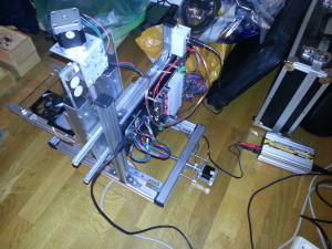
This is a CNC Machine I’ve built. It is capable of milling using a 100W 230VAC proxxon handheld multitool and laser engraving/cutting with a 1W 445nm diode laser. It mainly consists of parts from the hardware store and is actually low budget.
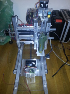
Front side with the milling tool in place and the 445nm 1W laser diode in an AixiZ module with its 800mA constant current regulator, CPU heatsink and fan for smoke removal.
The steppers (NEMA17, 1,6A) are driven by a TB6560-based 3Axis control board rated for up to 3A.
Our local hardware store around here had those awesome aluminum profiles, which are affordable, as well as easy to use. They make a very precise and stiff frame.
Exery axis works with standard drawer slides. Given the fact that they make dirt-cheap linear motion guides, the result is quite satisfying. There is, however, some play in the Z-axis when it’s fully moved out. When working with materials such as plywood, this doesn’t impair the precision, which is still in 1/10mm area. The overall working dimensions of the setup are 19cm in the X-axis, 30cm in the Y-axis and >8cm in the Z-axis, which is enough for DIN A4-sized materials.
The X-Axis uses a standard stainless M8 threaded rod with a long steel nut (never change a winning team ![]() ), whereas the Y and Z-Axes have been upgraded to 12mm Acme-Rods with 3mm pitch. The couplings are good ol’ Gardena garden hose tightened with hose clamps.
), whereas the Y and Z-Axes have been upgraded to 12mm Acme-Rods with 3mm pitch. The couplings are good ol’ Gardena garden hose tightened with hose clamps.
I’m using 2 different software plattforms, depending on what has to be done:
- over the parallel port: Google SketchUp with the Phlatscript plugin and LinuxCNC for milling
- over the GRBL G-code interpreter on an Arduino via USB: Inkscape with the laser engraver plugin and GcodeSender for laser engraving/cutting. A great description of this extremely useful toolchain can be found here: http://www.instructables.com/id/Pocket-laser-engraver/step7/Getting-the-software-ready
If the laser has to be used it has to be pluged into the red and black female jacks below the power supply jack (grey box on one of the columns). Otherwise they are used for the M03/05 command for switching the milling tool (see lower picture).
Some words on the development process
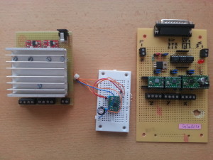
I’ve built 2 versions of driver boards for different purposes before. On the left of the picture below you can see an arduino “Laser Shield” based on 2 Easy Drivers (http://schmalzhaus.com/EasyDriver/) and a FET for switching the laser. Since te chips became very hot, I gave them a good heat sink. Some wires have been added to be able to have a Pololu driver control the Z-axis on a milling setup. The A3967 can deliver a maximum of 750mA per phase which was not quite sufficient for a milling setup, so I had to think further.
On the right you can see my optocoupler-isolated parallel port board for Pololu (A49xx) carrier boards. These drivers can deliver 2A per phase (with proper heat dissipation) which was better. A FET for laser control is also on board. For some reason The chip for the X-axis died (it sits on the carrier with the voltage regulator). I sampled some A4988 and replaced it twice, but that kept happening. That drove me nuts, so I decided to try a TB6560 based board.
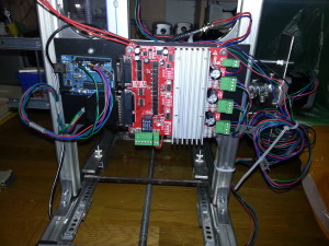
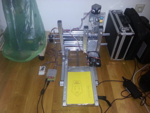
Here you can see the setup with the laser shield and the result on yellow paper. The board from ebay is by now also capable of driving the laser, so this is actually obsolete, but nice anyway 😉
Hello world!
Time to upgrade to a 21st century web page appearance!
www.thinkering.npage.de has finally completely moved to this new domain. All the content was dumped here within a couple of days in June 2014.
I hope you enjoy my new blog page.
